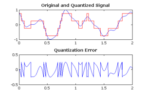
In Digital signal processing, Quantization noise for a 2-bit ADC operating is at an infinite sample rate. The difference between the blue and red signals in the upper graph, which is the quantization error. The source of the noise is “added” to the quantized signal.
Comparison of the sinusoidal wave of 6 bits and 8 bits are huge. The noise created by 6-bit quantization is 12 dB which is far greater than the noise created by 8-bit quantization. Quantization in the analogue-to-digital conversion noise is a model of quantization error. The analogue input is the round error. The voltage to the analogue-to-digital conversion and the output digitized value. The noise produced is a non-linear and signal-dependent which can easily be modelled in different ways.
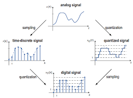
In Digital signal processing an ideal analogue-to-digital converter. This uniformly distributed between −1/2 LSB and +1/2 LSB is the quantization error. The uniformly distributed overall quantization levels signal.
The calculation is done Signal-to-quantization-noise ratio (SQNR)
SQNR = 20log2^Q = 6.02*QdB
- Q is the number of quantization bits.
The most common test signals that fulfil this are full amplitude triangle waves and sawtooth waves.
If the input signal is a full-amplitude sine wave then the distribution of the signal is not uniform. Conversely, the calculation of SQNR done.
SQNR = 1.761+6.02*QdB
16-bit ADC has a maximum signal-to-noise ratio of 98.09 dB. The 1.761 difference in signal-to-noise happens to the signal being a full-scale sine wave instead of a triangle or sawtooth.